Congratulations on your purchase of the GoFlight GF- TQ6 (Throttle Quadrant Module)!
The GF-TQ6 is designed to operate with a wide variety of simulated aircraft and is sure to make your flight simulation experience more realistic and enjoyable.
What’s included in the GF-TQ6 Package
After unpacking, please verify that your GF-TQ6 package contains the following items:
Quantity Description
| 1 GF-TQ6 Throttle System Module enclosure and control assembly |
| 1 2-meter USB Cable |
| 1 Hardware package containing: |
| * (4) Nylon 6-32 x 3/8” mounting thumbscrews |
| * (4) Adhesive-backed rubber feet |
| 2 Detent plates for jet spoilers and flaps |
The GF-TQ6 ships from the factory in a (4) thrust lever jet configuration, giving you the ability to realistically simulate the operation of an airliner with up to 4 jet engines. The leftmost lever is designed to resemble a typical airliner spoiler control and the rightmost lever is designed to resemble a typical airliner flaps control.
Rack and Custom Mounting
The GF-TQ6 is designed for direct installation into the GoFlight GF-AC Full Height Rack or the Flight
Deck Console (FDC) enclosures. Four 6-32 x 3/8” nylon thumbscrews are provided for this purpose.
If you wish to mount the GF-TQ6 into a custom cockpit, threaded 6-32 holes are provided on the bottom and rear panels of the throttle enclosure for custom mounting applications.
Flight Deck Console Mounting
When mounting the GF-TQ6 into the Flight Deck Console, GoFlight recommends that the GF-TQ6 be installed in the “corner” portion of the console. In this position, the GF-TQ6 will cover both vertical module bays and the two horizontal bays furthest forward. However, you can mount the unit in any desired location using the threaded holes located on the bottom and rear panels of the throttle enclosure.
To install the GF-TQ6 into the recommended location in the Flight Deck Console, do the following:
1. Remove any GF-AC cockpit control modules that may be mounted in the upper angled portion of the Flight Deck Console. This provides easy access to the rear panel of the GF-TQ6 for attachment of mounting screws and for USB cable connection.
2. Using two the 6-32 x 3/8” mounting thumbscrews provided, feed the screws through the top left
and right mounting rail holes in the vertical bay section of the console.
3. Align the back panel of the GF-TQ6 enclosure with the mounting screws, and tighten the screws until the GF-TQ6 enclosure is securely fastened to the console.
A similar procedure can be used to mount the GF-TQ6 in other locations in the console. There are four 6-32 threaded mounting holes on the bottom panel of the GF-TQ6 enclosure for this purpose.
NOTE: When tightening the GF-TQ6 mounting thumbscrews, be careful not to over tighten the screws as it is possible to strip the threads in the mounting
holes and/or break the mounting screws if excessive force is applied.
Connecting the USB Cable
To connect the GF-TQ6 to your computer, use the 2-meter USB cable provided in the package, following these steps:
1. Plug the USB cable “B” connector end (square) into the connector on the back of the GF-TQ6 enclosure.
2. Plug the USB cable “A” connector end (rectangular) to a USB port on your computer.
The first time the GF-TQ6 is connected to the USB port on a computer running Microsoft Windows, a message “New Hardware Found” may appear briefly on your screen. This indicates that Windows has detected the GF-TQ6, and has loaded all required drivers. From this point on, if you disconnect the GFTQ6 and then re-connect it, the drivers will automatically load but no message will appear on the screen. This also occurs each time you re-start your computer while the GF-TQ6 is connected. The automatic loading of the drivers with no notification message is a normal operating feature of the
Windows Plug and Play operating system.
NOTE: If you own other GoFlight hardware and have already installed the most current version of software on your system, you do not need to install the software again. Simply skip the software installation steps in the instructions below.
Software Installation
1. Using a web browser go to http://www.goflightinc.com.
2. On the GoFlight home page click “Support.
3. Click on “GF Config x.xx” to download the latest module drivers and configuration software.
4. Click “Run” or “Save” and follow the instructions to install the software.
If the software installer detects that GoFlight software is already installed on your system, it will prompt you to overwrite. Click the Yes button to overwrite the existing version of GoFlight software. This is useful if you wish to keep the configuration settings for other GoFlight
modules installed on your system. However, you should first make sure that the software you are overwriting is an older version and not a newer one
3. When the software installation is complete, a message box will appear, displaying the message
“Finished!” Click the OK button in this message box.
Main Control Lever Calibration
After connecting the GF-TQ6 to your computer for the first time, it is necessary to calibrate the six main control levers so that they have effect throughout their entire range of motion. After this process has been completed, you will not have to repeat the calibration steps unless you: (a) wish to change the lever response to suit different applications, or (b) install or remove other game devices attached to your computer.
Calibration and Operations Checkout on Windows Systems

For owners of computers running the Microsoft Windows operating system, control lever calibration is accomplished using the Control Panel applet called either “Game Controllers” (Windows XP or Vista). The steps on the following pages will guide you through the process of calibrating the GF-TQ6 control levers.
1. From the Windows Control Panel, start the Game
Controllers or Gaming Options applet.
2. Select the entry that reads “GFTQ6 Throttle System”,
then click the Properties button.
In this example, a GF-TQ6 Throttle Quadrant is connected to a Windows 2000 computer at the same time as a Microsoft SideWinder Precision Pro joystick. Both are USB devices.
3. After clicking the Properties button, the test and calibration panel for the GF-TQ6 is displayed. Below the GF-TQ6 control diagram are six colored bars showing the current positions of all the GF-TQ6’s main control levers (A-F.) Above the diagram are indicators showing the on/off states of each of the four switch levers (B-E.)
4. Using this panel, you can test and calibrate all six main control levers quickly and easily in a single pass.
To calibrate, simply follow the instructions displayed on the panel. Calibration is only required the first time you connect the GFTQ6 to your computer, and then only if you reassign its game controller ID or cause the ID to change by connecting or removing other game devices.

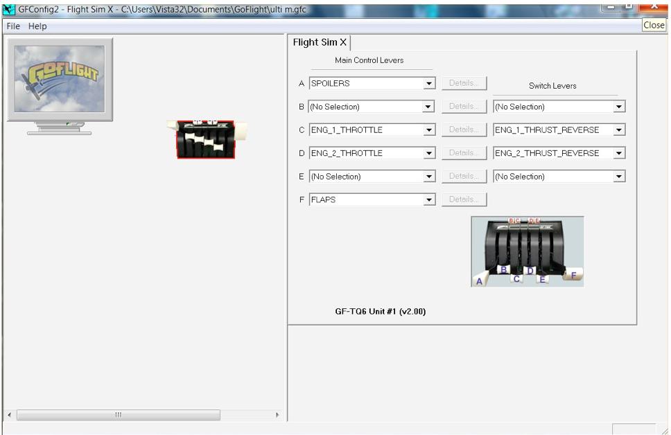
Flight Simulator Software Configuration
The GF-TQ6 can be used with a variety of flight simulator programs. This section explains how to
configure the GF-TQ6’s main control and switch levers for
use with some of today’s most popular flight
simulator programs.
Microsoft Flight Simulator 2004 and FSX
The GF-TQ6 is recognized by Microsoft Flight Simulator as a device type: ‘game controller’, and when detected for the first time, Flight
Simulator will create a “default” assignment for each of the control levers and switch levers on the GF-
TQ6. These initial assignments are usually not what you want, so you will need to use the
Controls/Assignments facility in Flight Simulator to reassign or un-assign the default functions.
GF-Config also allows you to assign functions to the GF-TQ6 control levers and switch levers, and we recommend that you use GF-Config to assign functions to the GF-TQ6 rather than using the Controls/ Assignments facility in Flight Simulator. The options available in GF-Config provide more control options than are available using the Controls/Assignments facility in Flight Simulator.
Typical six axis set up for TQ6

737 setup for TQ6-Advanced throttle
TQ6-Advanced TOGA and Auto Throttle Disengage setup
The TOGA or Auto throttle button can be programmed through Flight Simulator for the default aircraft. To program, go to settings, then controls, then click on the Buttons/Key Tab make sure that your TQ6 is in the controller type window. Now scroll down and find the TOGA function. Double click on the function then a box will come up asking you to hit a button. Hit one of the A/T buttons on your TQ6.Now the function is set. To Program the auto throttle Disengage for the default aircraft this button can be set in FSUIPC: The SETTING IS AP Panel Speed Off.
Other Software
For information on using the GF-TQ6 with other software programs, please consult our technical support resources available on the GoFlight Web site at http://support.goflightinc.com
Please be sure to also refer to the GF-TQ6 functionality as described in GFConfig Support Documentation
- under Help on the GF-Config menu bar, Select the Contents tab. Then select the GF-AC Function Reference and then select the GF-TQ6 Function Reference. Here you will find all the usable functions with their definitions and Usage Notes for the GF-TQ6 module
Installing and Removing Control Levers for TQ6
The six main control levers and four switch levers on the GF-TQ6 can all be removed and/or replaced so that you can realistically model the operation of throttle and other controls found in many types of aircraft.
For example, GoFlight offers an optional turboprop lever set including two power levers, two prop pitch
levers, and two mixture control levers that can be installed into the handle bases of the GF-TQ6. GoFlight also plans to offer additional lever and detent plate sets for your GF-TQ6 in the near future.
To reconfigure the control levers, follow these steps:
| 1. |
Disconnect the GF-TQ6 from your computer. You can disconnect either end of the USB cable, whichever happens to be most convenient. |
|
| 2. 3. |
If you plan to remove any of the four switch levers, first slide the switch lever(s) fully forward, then slide the associated main control lever(s) fully back. With the levers in this position, you can easily remove and insert the appropriate lever into its base with a firm straight motion upward along an imaginary line extending from the base mounting fixture. If you plan to remove any of the six main control levers, slide these levers to the full |
|
| forward position before removal. |
||
| If you plan to operate the GF-TQ6 without a control lever at any of these locations (e.g., a twin- jet configuration), lever bases without handles can be left “parked” in the full forward position, making it easier and more convenient to later re-install a lever. |
||
| 4. |
Re-connect the GF-TQ6 to your computer. |
Installing and Removing Detent Plates
Your GF-TQ6 ships from the factory with two detent plates than can be optionally mounted to the top panel of the GF-TQ6 enclosure. These detent plates provide stopping points for the control levers in the A and F positions. One of the plates is designed to provide detents for spoiler control, with stops in the Fully Retracted, Armed, and Operating Range positions. The other plate provides detents for up to
6 “notches” of flaps. Using GF-Config software, you can designate various control actions to occur when the control levers are placed each of the detent position, referred to in the software as “zones.” For more information about zone assignments, please refer to the GF-Config on-line help.
To Download a PDF Version of this Manual, click the link below: